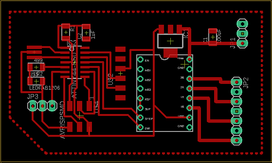
My electronic system consists of a pololu A4988 stepper driver and an ATTiny44 that controls the stepper and receives input from the pressure sensor.
Here are the components for the board:
Attiny84
Pololu A4988
5V regulator
Resonator
LED with resistor
programming interface with capacitor and pull up resistor at RST
input and output jacks
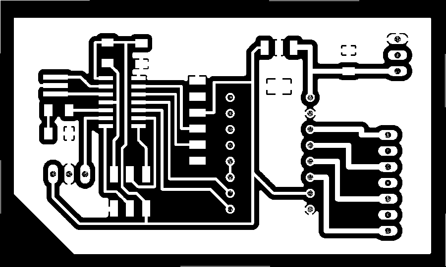
These are the board traces, you can see the ground plane that I used.
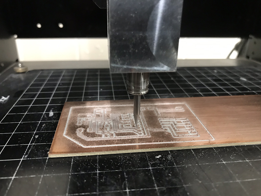
This the board being milled
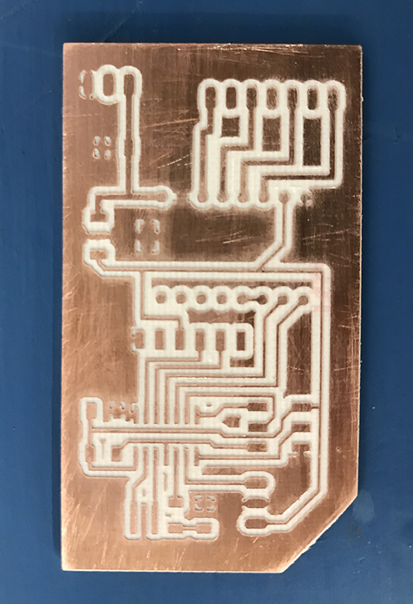
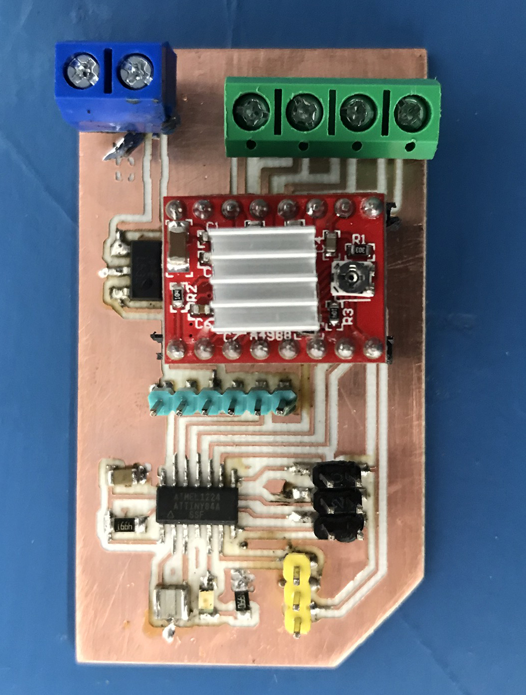
This is the finished board.
This is the board with all the components.
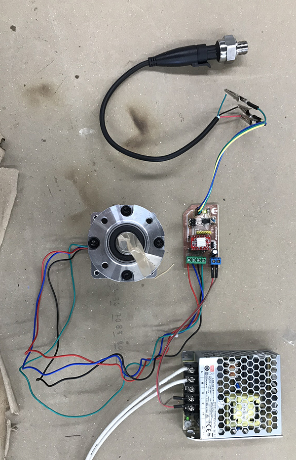
Finally this is the connected system, you can see:
24V power supply
Connected board
NEMA23 with planetary gearbox
Pressure Sensor connected to board
As you can see, the pressure sensor is working, and the motor as well. It actually took me 3 redesigns of the board, as well as several tries at soldering correctly.
This is the code for this test:
        const int dirPin = 3;
        const int stepPin = 2;
        const int ledpin = 8;
        const int steps = 9331;
        int stepDelay = 750;
        int pressure = A7;
        int val = 0;
        boolean gira = false;
        void setup() {
          pinMode(dirPin, OUTPUT);
          pinMode(stepPin, OUTPUT);
          pinMode(ledpin, OUTPUT);
        }
        void loop() {
          val = analogRead(pressure);
          if (val > 105) {
            digitalWrite(ledpin, HIGH);
            gira = true;
          }
          else{
            gira=false;
          }
          if (gira) {
            digitalWrite(dirPin, HIGH);
            digitalWrite(stepPin, HIGH);
            delayMicroseconds(stepDelay);
            digitalWrite(stepPin, LOW);
            delayMicroseconds(stepDelay);
          }
        }
LCD Screen
LCD1602
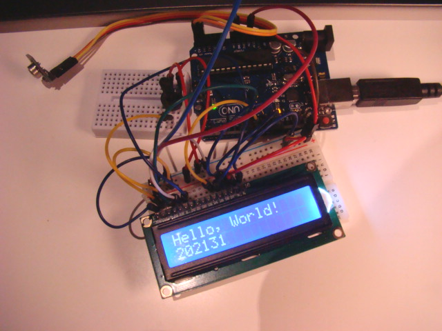
The LCD display is used in conjunction with a special library. The Library allows for communication with the LCD screen that has 16x2 character positions and are configurable with simple print commands. The screen is text based, so it's actually not a bitmap.
The connecction is quite complex, which is due to the fact that I haven't gotten my I2C adapter which would connect with just 2 wires. The connection has 8 data pins that are on or off and create the bits that you read or write from the screen.
The first thing I did was to get the Hello World Sketch Started.
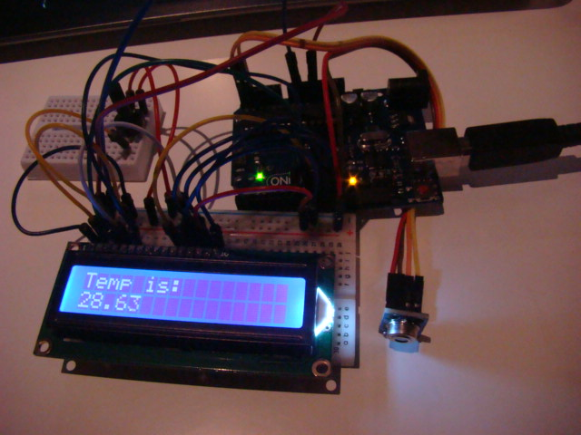
The second thing I did was to merge the first sketch from input devices week with this one, so that the display showed the temperature from the sensor:
I added a delay at the end of the sketch because the refresh rate was off. Heres a video with my finger and a glass of ice water. It was hot today!
Arduino Code
The Arduino code is made much easier with the LCD library, you only use the method lcd.print("message") to print text to the screen. You have to setCursor(x,y) to write a new line under the first line. Since the first one is static, it gets written in the setup.
I modified the example file that comes with the library, so that we get the value from the temperature sensor.
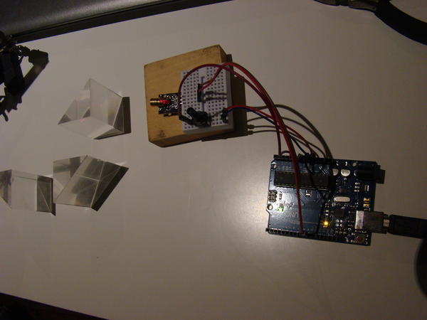
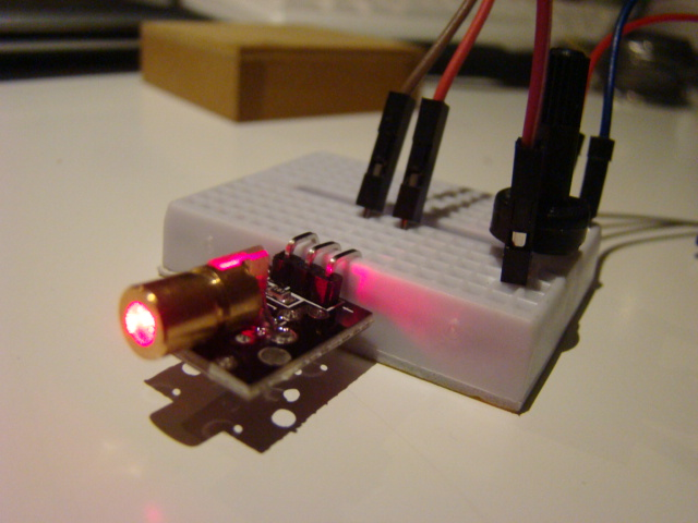
The KY008 laser module that I got just because it was super cheap, and it's a laser. It's the kind of laser you'd find on laser pointers and it was under a dollar.
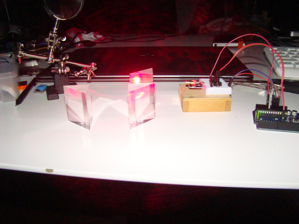
This module is a fine one to understand PWM. I used PWM to vary the laser intensity. PWM is a way of getting a continously varying signal from a signal that only has two states. By turning it on and off rapidly, the signal simulates voltages in between its on and off state. In this case, 5V. We get a laser that varies in intensity over time just by changing a delay value. I hooked it up to a potentiometer just to have more control. I set it up with some acrylic prisms that I have and got some nice patterns. I should have gotten special eye protection which is the reason why I only played around with the lasers for a little while. This is the code:
I want to set the laser up with an LED as a light sensor and get a laser tripwire. I didn't have time, but I think that setting up the laser with an LED would be a very precise tripwire.
In the video you can see the laser interacting with the prisms, and the PWM in action by way of changing the duration of the on period, which is called "duty cycle".
My electronic system consists of a pololu A4988 stepper driver and an ATTiny44 that controls the stepper and receives input from the pressure sensor.
As you can see, the pressure sensor is working, and the motor as well. It actually took me 3 redesigns of the board, as well as several tries at soldering correctly.